![]()
FRP Tank Linings Inspection Report
Tank Name/Contents- Sodium Hypochlorite FRP Tank Linings
Table of Contents
1 Definitions 3
2 Scope and methods 3
3 Summary of Issues & Recommendations 4
4 Barcol Hardness Measurements (ASTM D 2583) 11
5 Appendix A: General Information on FRP 13
6 Appendix B: Conversion Curves for Barcol Values 18
7 Appendix C: Drawings, Name Plate, Labels 19
8 Appendix D: Additional Pictures from the inspection 21
9 Appendix E: Repair Methods to reline FRP Tank surfaces (i.e. replace 100 mil thick corrosion barrier) – a brief outline 23
10 Appendix F: Detailed Repair Procedure to reline FRP Tank surfaces 24
11 Appendix G: Severe Cases of Chemical permeation and resin degradation 27
12 Appendix H: In-place Dome Replacement with Structural MRM layers 31
Definitions
- FRP: an acronym for Fiber Reinforced Plastic, commonly known as fiberglass
- Fiberglass layers
- M = 1.5 oz (per sq ft) Chopped Strand Mat
- R = 24 oz (per sq yd), woven roving
- V = Veil, Nexus (organic polymer) or C-Veil (SiO2 based)
Scope and methods
Only non-destructive techniques were utilized for this inspection. Two methods were employed:
- Visual FRP tank linings inspection
- Barcol Hardness tests (ASTM D2583)
- Wall Thickness (very limited correlation to degradation of FRP)
Referenced Standards
- The repair methods should be based on the following standards
- ASTM C582-09 Standard Specification for Contact-Molded Reinforced Thermosetting Plastic (RTP) Laminates for Corrosion-Resistant Equipment
- ASTM D2583 Barcol Hardness
Summary of FRP Tank Linings Issues & Recommendations
# Issues Recommendations
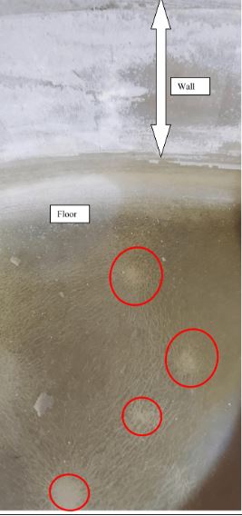
- Star burst pattern may be an indication of stresses on the floor. Must reinforce the floor with 2(MRM) layers on the order of 1/4” thickness. Per the drawing, the floor thickness of structural MRMM layers = 0.162”. The Corrosion Barrier thickness = 0.116”.
The absence of exposed Chopped Strand Mat (M) layers (as a reference, see Appendix for an illustrative example of a severe case) shows the degradation is limited to the surface 100 mil (0.1” nominal thickness of Corrosion Barrier) and that the structural MRMM layers under are intact.
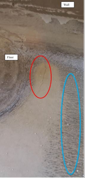
- Surface cracks on the floor indicate the floor needs to be reinforced with 2(MRM) layers on the order of 1/4” thickness. Per the drawing, the floor thickness of structural MRMM layers = 0.162”. The Corrosion Barrier thickness = 0.116”. The lighter color (yellowish) against the much darker original resin color indicates chemical permeation in to the corrosion barrier through the surface crack. Note how the lighter color is solid (RED circle in the picture) close to the crack and then shows up as squiggly lines (BLUE circle) that are channels in the 0.1” thick Corrosion Barrier through which the chemical has permeated.
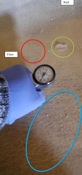
- Surface cracks on the floor are seen throughout the floor. The Barcol Hardness readings were acceptable (Reading of 40 in the picture here, Specifications > 30).
The GREEN circle shows one of the many chunks of the wax layer that is strewn all over the floor which is of no concern for the FRP layers except that it could be a mechanical nuisance that the filters in the pipe system should be able to take care of. The wax layer is NOT an integral part of the FRP layers (See Appendix A for a cross-sectional sketch of FRP). It is simply used to help in the cure of the FRP layers. This it does by acting as a barrier to oxygen which retards the polymerization between the resin and the initiator/catalyst commonly referred to as “curing”.
- A surface crack at another spot on the floor closer to the knuckle / shell wall. New structural MRM layers will be needed on the floor to fix this issue.Theoretically, an extreme case of a structural crack is a gaping hole in a tank. Even such cases are repairable with MRM layers that mimics the OEM’s fabrication method for the floor which is based on ASTM D4097 (Hand Lay Up method mentioned in the Tank Drawing – See appendix C). An illustrative example of this is shown in Appendix H: In-place Dome Replacement with Structural MRM layers.
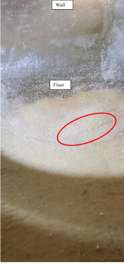
- The RED circle in the internal FRP joint/band that is about 30” wide along the internal circumference of the tank walls shows the light patch that is a result of resin degradation from chemical permeation into the corrosion barrier.
Shell wall’s 0.1” thick corrosion barrier should be relined with MMVV layers up to about a 5-foot elevation i.e. the new corrosion barrier of MMVV should span the entire floor and 5 feet up on to the shell wall.
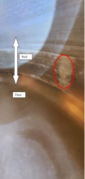
- The RED circle in the internal FRP joint/band shows the light patch that is a result of resin degradation from chemical permeation into the corrosion barrier.
Shell wall’s 0.1” thick corrosion barrier should be relined with MMVV layers. Suggested height of the reline = 5 ft on to the wall.
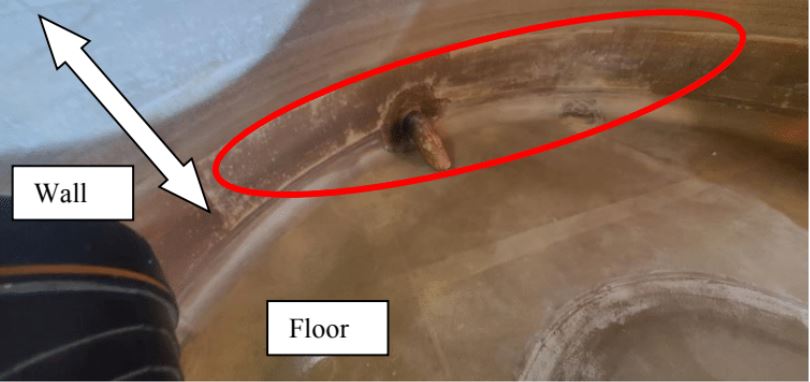
- Optional Repairs: The area above a 5-foot elevation shows some chemical permeation albeit not to a severe extent. The repairs to this portion may be postponed to about 5 years into the future. It is safe to presume that at that point, the corrosion barrier would need to be relined with MMVV layers.
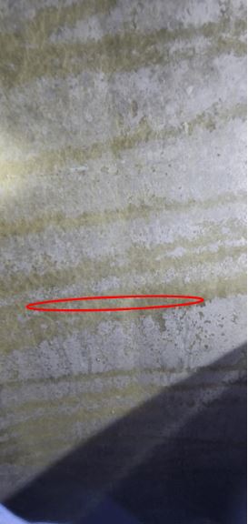
The white layers on the surface are not a result of FRP degradation but simply chemical deposition of the stored chemical. Note that the layer under the whitish chemical deposits are bright and glossy which indicates the resin – which gives chemical resistance – is still present at an acceptable level.
Barcol Hardness Measurements (ASTM D 2583)
The Technique:
Barcol Hardness is an indentation technique that measures the hardness of FRP and is a standard hardness measurement in the FRP industry. It is normally used to measure the degree of cure during fabrication or repairs but, could also be used to determine if the underlying layers have lost its hardness due to severe chemical degradation. Although low Barcol values will indicate an issue, the reverse may not be true.
Appendix B shows a correlation between Barcol values and other hardness measurement methods such as Rockwell and Brinnell. Correlations below a Barcol value of 35 cannot be established due to the physical characteristics of soft materials that render uniform correlation between different hardness measurement systems very difficult.
Specifications:
The minimum expected value is 30. This is after adjusting for the Veil layers that would reduce the Barcol by a value of about 5. As a reference, the minimum expected for the pure, fully-cured resin (without Veil layers in the FRP) is 35.
Measurements:
Barcol values were measured on the floor and on the wall up to an elevation of 5 foot (within accessibility). The Barcol values were excellent and ranged from 35 to 45.
Conclusions:
The Barcol hardness values meet specifications. This complements the lack of evidence of any degradation of the chopped strand mat (M) or the structural FRP layers underneath the corrosion barrier.
| Figure 5: Barcol Hardness measurements were acceptable and all readings were in the 35-45 range (Specification >30). This indicates the FRP layers are “hard” underneath despite the surface cracks. There is no evidence of significant structural issues on the floor emanating from chemical degradation of the FRP layers from the surface cracks. If the cracks were deeper than 0.1” and beneath the corrosion barrier, the chemical would typically degrade the structural layers. The structural layers have only 30% resistance compared to 90% for the corrosion barrier (See Appendix A for details of the constituent parts of the FRP layers. A lower reading far below the specified values for the hardness would have indicated a “softer” and therefore, degraded layer underneath. |
Appendix A: General Information on FRP
- As the name suggests, Fiber Reinforced Plastic (FRP), consists of Fiber (also known as glass) and Plastic (made of a thermoset polymer/resin). In broad terms, the fiber gives the mechanical strength and the resin gives the chemical resistance.
- Since it is difficult to achieve both mechanical strength and chemical resistance with a single composition, FRP is typically designed to have two main layers as illustrated in the schematic below.
- Layer #1 (corrosion barrier): This layer on the surface is in contact with the chemical stored in the vessel and therefore, provides the chemical resistance component. This layer is sometimes referred to as the chemical resistant liner. Since the chemical resistance is directly proportional to the resin content (at least as a first order approximation) this layer that contains 90% resin on average effectively has ~ 90% chemical resistance on a relative scale. The thickness of the corrosion barrier is typically 100 mil.
- Layer #2 (structural layer): This inner layer provides the mechanical strength for the vessel. Due to the low resin content, the chemical resistance of this layer is on the order of 30% on a relative scale. The structural layer is at least ¼” thick but is a lot more vulnerable to chemical attack once the chemical molecules permeate through the corrosion barrier and gets to this low-chemical resistant structural layer.
- Since the chemical resistance of the structural layer is only 30%, it is imperative that degradation of the corrosion barrier – which is inevitable in the presence of chemicals – is restored through a program of inspection followed by repairs or “relining” of the corrosion barrier.
- In a reline, the corrosion barrier layer is removed – usually with turbo shears specifically designed for FRP – and replaced with a new corrosion barrier.
- The corrosion barrier and structural FRP layers are shown in Figure A below.
![]()
FRP Tank Repair for Chemicals
Chemical Service
- A premium-grade vinyl ester resin that is typically used to fabricate FRP tanks is expected to make the corrosion barrier last 15-20 years. With relining of the 100-200 mil corrosion barrier the tank could last 50+ years.
Structural Layer
- The structural layer should be protected from chemical attack due to its weak chemical resistance. Over the years, the chemicals will permeate and deplete the 100 -200 mil corrosion barrier of resin. Once this barrier is penetrated, the structural layer, with its limited chemical protection will deteriorate very rapidly. Therefore, any issues with the corrosion barrier should be fixed promptly.
Corrosion Barrier
- The corrosion barrier – which is also referred to as the liner – is typically made of two layers of chopped strand mat (1.5 oz. per sq. ft.) and two layers of veil to make up the 100 mil thickness that is a typical minimum. Thicker corrosion barriers (eg. 200 mil) may be used for longer life of the corrosion barrier. This is achieved by using 4 layers of chopped strand mat and 2 layers of veil.
Resin system
- The industry workhorse resin for chemical vessels has for a long time been Derakane 411
- The recommended catalyst system is MEKP or BPO/DMA (for NaOCl).
Permeation of the chemical stored
- The figure below shows the eventual permeation of Chemical molecules to the structural layer. If this situation is not attended to urgently one could be saddled with costly repairs to the structural layer.
![]()
Relining to extend the life of the vessel
- With a relining program, the life of any FRP tank can be extended beyond 30 years. Over time, the liner in FRP tanks will erode from the mechanical abrasion and chemical reactions with the tank contents. Excursions in pH and temperature will accelerate the process. Here are typical reline intervals:
![]()
Severe Conditions
- Note as indicated above, how for the same chemical (12%-15% NaOCl) the reline intervals can be dramatically different depending on the service conditions. It is almost double for transport tankers compared to storage vessels.
- The transport tankers undergo high stress conditions created from freeway sloshing, frequent loading/unloading of chemicals and sun exposure. These conditions accelerate the degradation of the chemical resistant liner/corrosion barrier by rendering the tankers vulnerable to permeation and stress-induced resin crazing. Resin crazing/cracks will create a wide path for the stored chemical to get through the corrosion barrier and into the structural layer.
For storage tanks, the stresses are highest at the knuckle area where the tank floor meets the straight shell.
![]()
Correlations below a Barcol-Coleman Impressor Number of 35 (x-axis in above graph) cannot be established. This is due to the physical characteristics of soft materials that render uniform correlation between different hardness measurement systems very difficult.
Appendix C: Drawings, Name Plate, Labels
![]()
Appendix D: Additional Pictures from the inspection
![]()
![]()
Appendix E: Repair Methods to reline FRP Tank surfaces (i.e. replace 100 mil thick corrosion barrier) – a brief outline
Contractor Qualifications
A contractor with experience of relining at least 5 industrial chemical tanks and with a State of California C61-D12 license must be used to minimize FRP workmanship issues.
Materials and Methods
- Resin/catalyst system
- Premium-grade, vinyl ester resin such as Derakane 411 or 510A-40 resin
- BPO / DMA catalyst (must be Cobalt-free for NaOCl)
- Fiber Reinforcement
- M = 2 layers of 1 ½oz chopped strand mat
- R = 24 oz Woven roving (5×4 weave pattern)
- V = C Veil or Nexus
- Layers
- Corrosion Barrier: MMVV.
- Structural: MRM (if needed)
- Wax
- A resin “wax” coat shall be applied after lamination to provide a cured surface.
- Curing
- A high temperature post-cure
- Quality Control
- ASTM 2583 Barcol Hardness Test
- Acetone Sensitivity Test
- Standards
- ASTM C582: Standard Specification for Contact-Molded Reinforced Thermosetting Plastic (RTP) Laminates for Corrosion-Resistant Equipment
- ASTM D4097: Standard Specification for Contact-Molded Glass-Fiber-Reinforced Thermoset Resin Corrosion-Resistant Tanks
- ASTM 2583: Standard Test Method for Indentation Hardness of Rigid Plastics by Means of a Barcol Impressor
For Nozzle Replacement / FRP Joints
- FRP overlay widths should follow ASTM D4097 standards
- Cutout reinforcement diameter must be greater of 2d or d+6 in. where d = ID of flange.
Appendix F: Detailed Repair Procedure to reline FRP Tank surfaces
Scope
- The instructions described in this document are intended to provide directions and guidance for the repair of an FRP tank. Specifically, the procedure will address the following repairs:
-
- Repairing flanged nozzles
- Replacing the corrosion barrier
- Additional FRP structural reinforcements
-
- Standards
-
- ASTM C582: Standard Specification for Contact-Molded Reinforced Thermosetting Plastic (RTP) Laminates for Corrosion-Resistant Equipment
- ASTM D4097: Standard Specification for Contact-Molded Glass-Fiber-Reinforced Thermoset Resin Corrosion-Resistant Tanks
- ASTM 2583: Standard Test Method for Indentation Hardness of Rigid Plastics by Means of a Barcol Impressor
- ASTM D5421: Standard Specification for Contact Molded “Fiberglass” (Glass-Fiber-Reinforced Thermosetting Resin) Flanges
-
- May be used with the approval of the project owner
Safety Precautions
CAUTION: All mixtures are flammable. Keep away from sparks and open flame. Work where adequate ventilation is available.
WARNING: Avoid prolonged contact with skin. Wash thoroughly after handling and before eating or smoking. Keep container closed when not in use. Wear proper PPE as directed in the MSDS. If swallowed consult a doctor immediately.
USE WITH ADEQUATE VENTILATION: Ventilation must be adequate to maintain air-borne concentrations of vapors below threshold limit values (TLV)
Consult material supplier safety data sheets (SDS) for additional safety information.
3.0 Definitions
- Fiber Reinforcement
- M = 1 ½oz chopped strand mat, nominal thickness = .045”
- R = 24 oz Woven roving (5×4 weave pattern), nominal thickness = .035”
- V = C-Veil, nominal thickness = .010”
- Laminate – FRP layer that consists of resin plus fabric.
- Wax – a surface agent added to resin to be used for the top layer.
- Thickness – all thickness values are nominal and construction minimums
4.0 Materials
- Paint brush
- Rollers
- Resin –Derakane 411 or 510A resin, a vinyl ester resin. Product name is Derakane 510A-40. It is manufactured by Ashland Chemical Inc.
- BPO / DMA catalyst/initiator
- Putty
- Fabric – chopped strand mat, woven roving, C-Veil
- Gel Coat – has UV protecting pigment
5.0 Pre-requisites to fiberglass lamination
- Dew point is at least 5 degrees below the substrate and ambient temperatures.
- No water/moisture should come in contact with the joint area until fully cured.
- Surface preparation is very important – no moisture, oily substances that inhibit adhesion
- Laminators/Applicators w/ at least 5 years of experience w/ vinylester resin lamination
DESIGN AND REPAIR REQUIREMENTS:
- The repairs shall conform to the latest edition of the following standards:
ASTM C582 American Society for Testing Materials
PROCEDURE – FRP Tank Linings Internal Repairs
-
- Prepare surfaces:
- Areas to be relined must be clean and free of moisture, dirt, oils and waxes.
- Sand all joint areas to approximately 1” beyond the area of lamination to roughen the surface and to remove the waxy resin surface.
- The recommended tool for this operation is an angle grinder / power sander using aluminum-oxide and a 4.5” diameter #16 – #36 grit sanding disc. Turbo-shears that have metal blades may be used if the entire thickness (usually, 100 mil) of the corrosion barrier has to be removed.
- Prepare Resin
- Prepare resin w/ catalyst
- Lay out/wet-out the fabric and apply resin
- The joint fabric material is laid out on heavy paper (cardboard is a good, practical option). Mylar or Saran may also be used, but do not use waxed paper for wet-out.
- Prepare Laminates
- For the MRM sandwich layer preparation, first put some resin on the cardboard. Then lay out the mat (M) and woven roving (R). Wet out with resin until saturated. Then put the remaining Mat (M) layer on top. Apply resin over the Mat (M). Saturate w/ resin to make one MRM laminate.
- Install Structural Layers per drawing Dwg # S154, Note 5
- Reinforce the floor with structural MRM layers
- Apply two groups of MRM laminate layers in a sandwich construction to the prepared surface.
- This will give a minimum nominal thickness of 0.2”
- Reinforce the floor with structural MRM layers
- Install Corrosion Barrier Layers per drawing Dwg # S154, Note 3
- To 5 feet elevation along the shell wall and 2 feet into the duct internal walls and the entire floor
- Apply MMVV
- Apply 2 layers of a 1 ½oz/ft2 fiberglass mat followed by 2 layers of C-Veil to give a nominal thickness of 100 mil
- Cure
- After the resin has hardened, a resin “wax” coat should be applied to provide a fully cured surface.
- A post-cure heat is required
- Prepare surfaces:
QUALITY CONTROL
-
- Barcol Hardness Test (ASTM D2583)
- A Barcol of at least 90% of manufacturer’s published value should be obtained after cure.
- Acetone Sensitivity Test
- Use acetone and clean rags to rub the cured surface
- Tacky or sticky surfaces indicate inadequate cure
- Barcol Hardness Test (ASTM D2583)
Appendix G: Severe Cases of Chemical permeation and resin degradation
FRP Layers – A pictorial description
![]()
![]()
![]()
![]()
Appendix H: In-place Dome Replacement with Structural MRM layers
![]()
You must be logged in to post a comment.